
3. Compile & Edit the Map

In this third part, we will create an OpenOrienteering Map with 'UTM' georeferencing and load the intermediate files we created in section 2. We will then perform some useful steps and save the files to a single folder.
3.1 OpenOrienteering Mapper
- Open the OpenOrienteering Mapper program.
- Click "Create a new map".
- Select "ISOM 2017-2_10000".
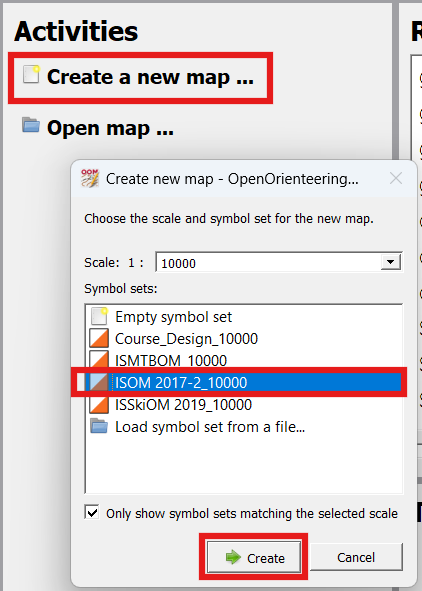
- Click "Create".
NOTE: The left-hand side of OpenOrienteering Mapper allows you to edit your map (it is grayed out until we add data). The right-hand side shows the "Symbol" window for adding objects to your map. Along the top is a toolbar that lets you select what action you want to do, adding, editing, rotating, cropping, etc. For additional help consult the online documentation page.
NOTE: In OpenOrienteering Mapper, there are two different ways to load intermediate data files: (1) loading an image file for viewing/comparing with the map, and (2) importing data, which allows us to edit the symbols/objects later on. An image cannot be 'imported', it must be loaded as a 'template'.
Only some files like shape files, can even be 'imported' vs loaded as image 'templates', but the distinction is worth explaining further. If you were to (incorrectly) load a contour shape file as an image or 'template', you would be able to see it and adjust transparency, but you would not be able to edit individual contour lines. To delete some points on the line, make subtle changes, etc, be sure to 'import' the data, and not use 'load as template' function.
3.2 Import OSM File(s)
We will begin by importing OpenStreetMap (OSM) data into our map.
- Click "File --> Import".
- Select the "OSM" file in your Park folder. In our example, it was called "map (1).osm"
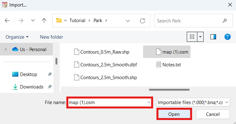
- Click "Open".
- On the "Map Georeferencing" window, under "Coordinate reference system", select "UTM".
NOTE: Changing the coordinate reference system of your map is something you should only do before you start mapping and importing data. This is because the coordinate reference system is critical to the location data of the map, and if you decide to change it up later on, it's probably going to make it difficult to properly import data afterwards, or stuff that is already on your map may be dislocated elsewhere. When I have selected "- local -" before, it has caused problems when I try to load templates, and they don't appear where they should be. For these reasons, I recommend always picking the simplest option, "UTM".
- Check that the "Status" indicates "Valid".
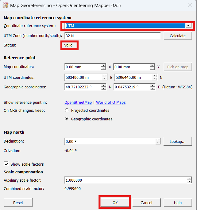
- Click "OK".
- On the "Assign new symbols" window, click "OK".
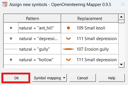
- We should now see some vectorized OSM data on our map.
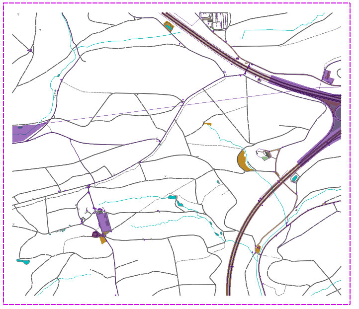
- Select "File --> Save" and save the map with the park name in the 'Park' folder. In our case we will save this map file as "Park" and it has an OMAP file extension.
NOTE: If you only have one OSM file, that concludes this section. If you have additional OSM files to download and patch together, or decided to add a new section of land to your pre-existing map and have a new OSM file you want to import, proceed with the below steps.
- Import the next OSM file.
- Examine where the "split" line was located at on the map screen.
NOTE: If you need to reference UTM coordinates while scanning the map, select "View --> Display coordinates as… --> UTM coordinates". The coordinates are visible in the bottom-right hand corner of the map as you move the mouse.
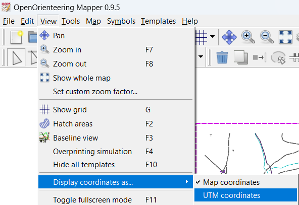
- From one end of the split line, working to the other end, select any two objects of the same type that were split (hold shift while selecting).
- Press 'C' to connect two linear features, or 'U' (union) to join two area features.
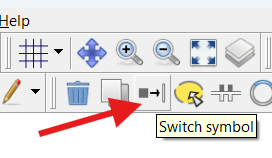
NOTE: If the two features are not the same type, they are not joinable. To change an object from one type to another, select the object, then select the type that you wish to change it to, then select the "Switch Symbol" function (also listed in the Tool menu).
NOTE: If you have already curved linear features, you may prefer to curve the additional lines before you connect them. To curve lines, select a linear feature and press 'N'. See this XXX section for tips concerning the curve function. /// (Curving lines may or may not help conserve memory; you'll need to experiment what works.)
- Continue to connect linear and join area features until you reach the end of the split line.
- Select "File --> Save" to save the map in the park folder.
- At this point, repeat the last five steps until you have imported all the OSM files.
3.3 Create Map Parts
RECOMMENDED STEP
Separating the map into various parts is a recommended step which will probably make editing easier. When we want to edit certain parts of the map, having different types of objects in separate parts will prevent us from accidentally selecting or making changes to other objects. Create map "parts" for at least the following categories:
- Topos - for topographic lines.
- Vegetation - for any vegetation areas we add later on.
- Purple - for purple lines, dots, areas.
- Grid - for magnetic north lines and other special objects like a bar scale.
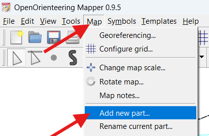
- Click the menu option "Map --> Add new part…".
- Enter "Topos" and press "OK".
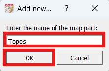
- Repeat the last two steps to create map parts "Vegetation", "Purple" and "Grid".
- Look at the top menu bar to see which part of the map we're currently editing.
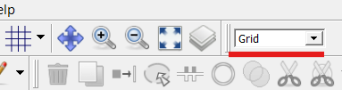
NOTE: If the part we just created is selected, we won't be able to select or edit anything because the objects are in a different part.
- Change the map part from whatever it is to "default part", which will allow us to select and move/edit the objects already on the map.
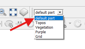
NOTE: You can add new parts at any time later in the mapping process, even temporarily in order to move a large quantity of objects around. When you're done with moving the objects and you want to remove the part, select the part, then select "Map --> Remove current part". You can even merge different parts together.
- Select "File --> Save" to save the map in the park folder.
3.4 Purple Part
There are several purple objects on the map that we imported from OpenStreetMap. To make editing other objects easier, we will move all the purple objects to the Purple part.
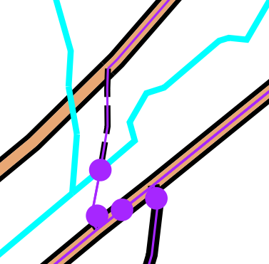
- Click the 'Edit Objects' (arrow) button at the top left.
- Select a purple line.
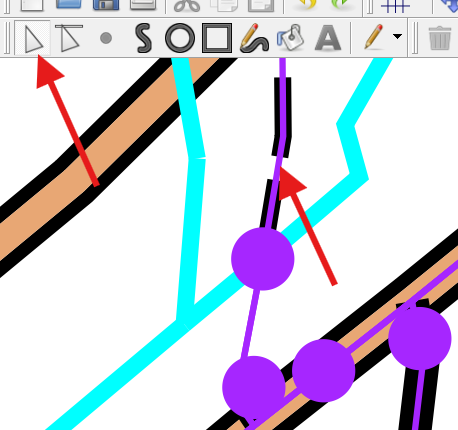
- Select "Edit --> Select all objects with selected symbols".
- Select "Map --> Move selected objects to --> Purple".
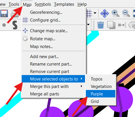
- Repeat the same process for all purple dots, and purple areas.
- Change the map part from whatever it is to "default part".
All the purple stuff should now be in the Purple part, therefore we don't need to worry about accidentally selecting the purple stuff when we want to edit other stuff.
- Select "File --> Save" to save the map in the park folder.
3.5 Topos Part & Contours
NOTE: In OpenOrienteering Mapper, there are two different ways to load intermediate data files: (1) loading an image file for viewing/comparing with the map, and (2) importing a (certain type of) file allowing you to edit the symbols as you would an orienteering map. For this step we will 'import' the 2.5m smoothed contour shape file, so the lines remain editable.
- Change the map part from whatever it is to "Topos".
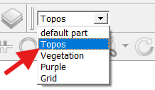
- Click "File --> Import".
- Select the "Contours_2.5m_Smooth.shp" file in your Park folder.
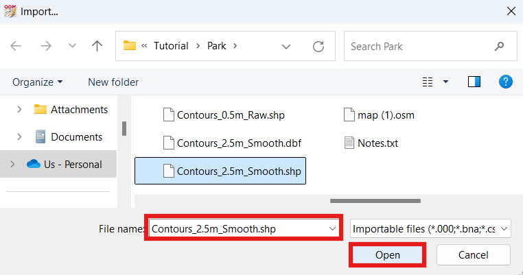
- Click "Open".
- On the "Assign new symbols" window, change the "Replacement --> 2 Line" to "101 Contour", and click "OK".
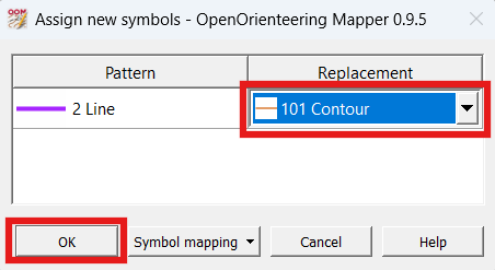
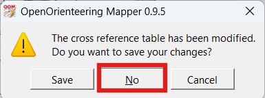
- Click "No to the prompt "The cross reference table has been modified. Do you want to save your changes?"
- Our map now has some soft contours, and looks wonderful!
- Change the map part from whatever it is to "default part".
NOTE: When in the 'default part', you should not be able to select any contour lines, because they should be in the 'Topos' map part. If contour lines are present in the 'default part' you may have skipped the first step in this section. You can move all the topos from default part to Topos part by selecting one, then selecting "edit --> Select all objects with selected symbols" then selecting "Map --> Move selected objects to --> Topos".
- Select "File --> Save" to save the map in the park folder.
3.6 Other Templates & Images
In this step we will load the remaining intermediate image files we created in the previous section. We will load them as 'templates' which means we can hide them, change their transparency, change their z-order (appearance order), but we will not be able to edit the images themselves in OpenOrienteering mapper.
It's important to note that when we save the OpenOrienteering map, it will not save all the images into the map file, but just include references to the image files. For this reason I recommend placing all the templates/images in the same folder (or subfolder) as the map file itself. In our example, our OpenOrienteering map file is in the Park folder, and that's also where all the images/templates are. When you prepare to conduct field checking and go to copy some of the map files to your mobile device, OpenOrienteering mapper on your mobile device will know where to find them, because they're all in the same folder.
- Select "Templates --> Template setup window".
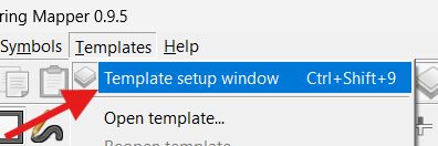
- Click the "Add template… (green plus) button.
- Click "Open…" on the bottom left of the Template setup window.
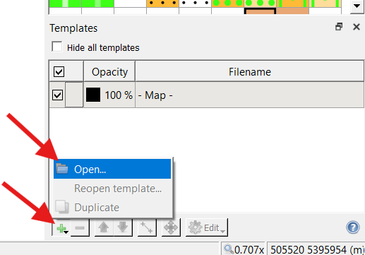
- Select the "Altitude.png" image and click "Open".
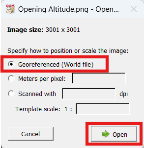
- At the "Specify how to position or scale the image" prompt, select "Georeferenced (World file)".
NOTE: If this option is grayed out, the World file (PGW extension) associated with the image may be missing. To create another one, you may have to repeat the steps to create the image (and world file) in the previous section.
- Click "Open".
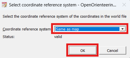
- At the "Select the coordinate reference system of the coordinates in the world file" prompt, select "Same as map" (which should be UTM).
- click "OK".
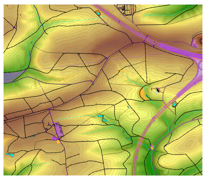
- Your map should now show the correct 'Altitude.png' image behind the map (brown areas are higher elevation, green areas are lower elevation).
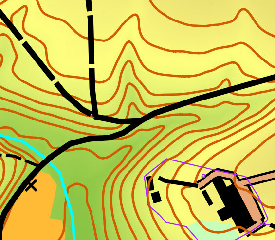
- Repeat the previous nine steps to open the template/image "Treetops.png".
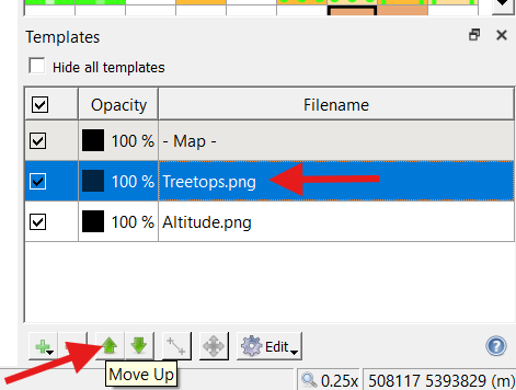
- Note that "Altitude" is higher in sequence than "Treetops" in in the Template Setup Window.
- Click the "Move up" (up arrow) button until "Treetops" appears first in sequence beneath "- Map -".
- The 'Treetops.png' image behind the map. The Treetops template may help us to see the location of unmapped trails or buildings. (brown areas are higher elevation, green areas are lower elevation)
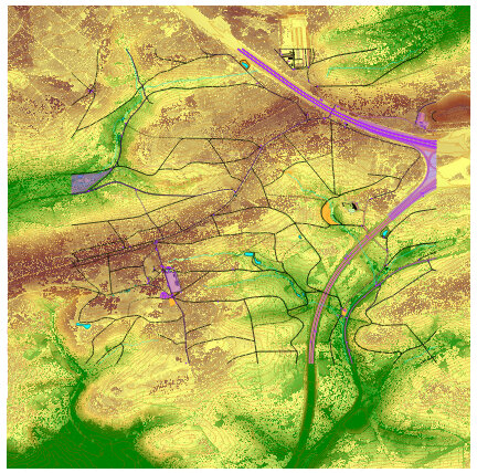
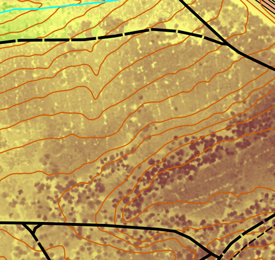
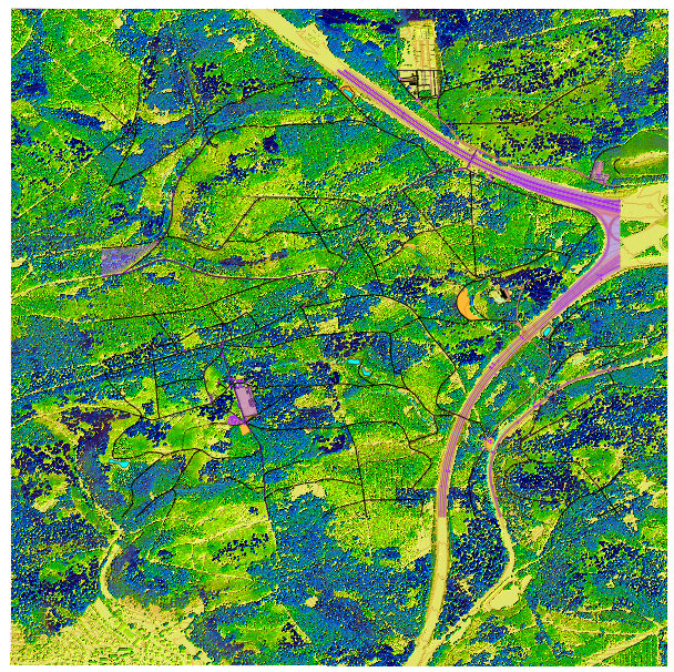
- Open the "Vegetation_Height.png" image using the above procedure.
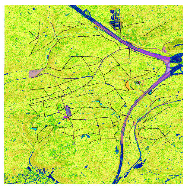
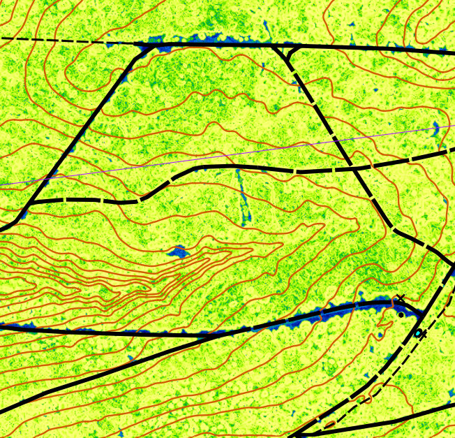
The 'Vegetation_Height' template may help us to map the vegetation (ground or short vegetation is yellow/green, taller vegetation is green/blue)
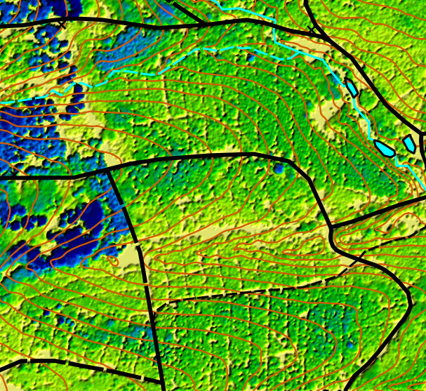
- Open the "Vegetation_Slope.png" image using the above procedure.
The 'Vegetation_Slope' template may help us to map vegetation boundaries better
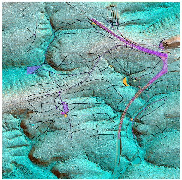
- Open the four "Hill_Shading_XXX.png" images using the above procedure.
The 'Hill_Shading_XXX' templates are helpful to identify micro-terrain features (when zoomed in). On the right, we see a probable unmapped trail or narrow ride, depending upon what it looks like in person.
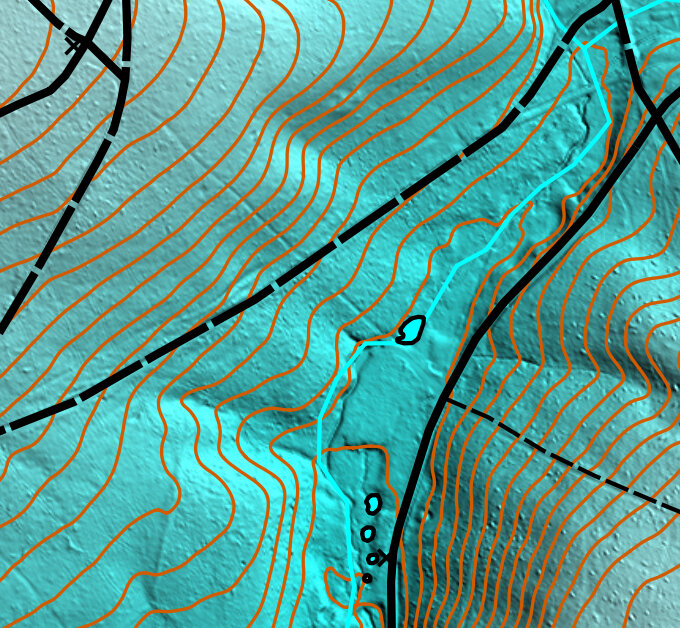
On the right, we see what could be a few historical roads. The road running along the ridge might be more visible on a different Hill_Shading image.
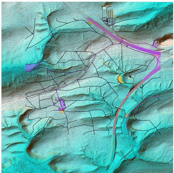
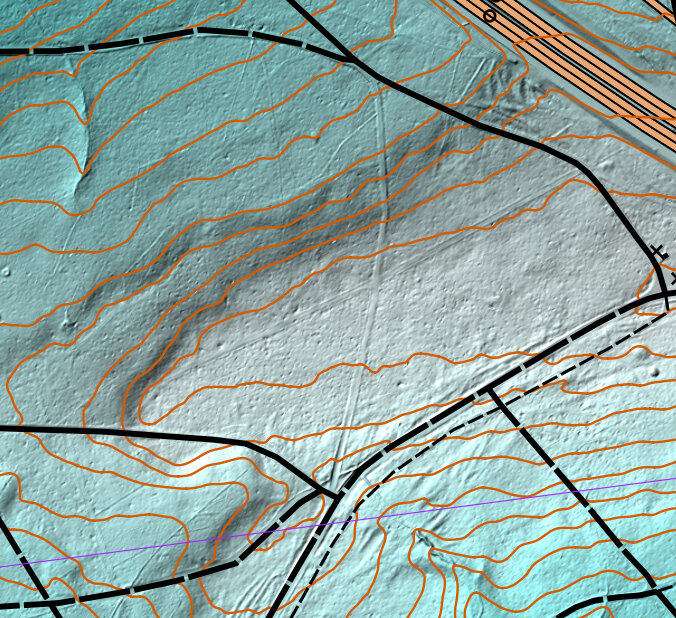
On the right, we see a few pits or small depressions nearby the road.
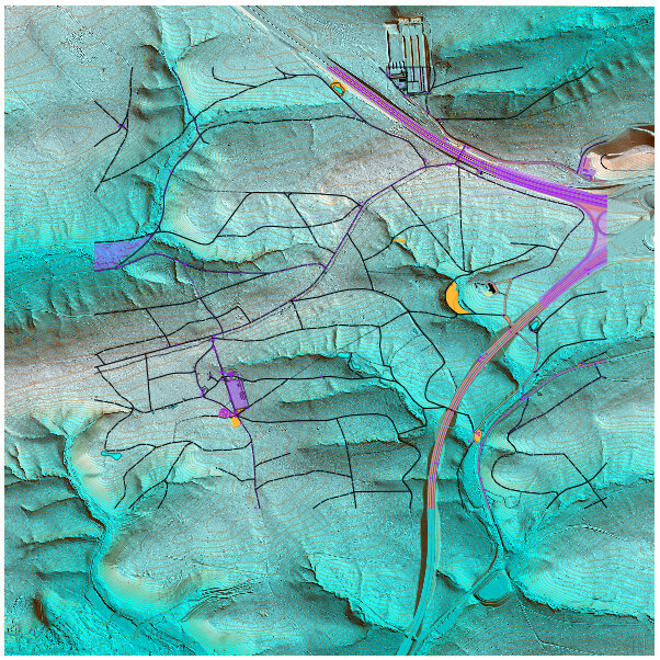
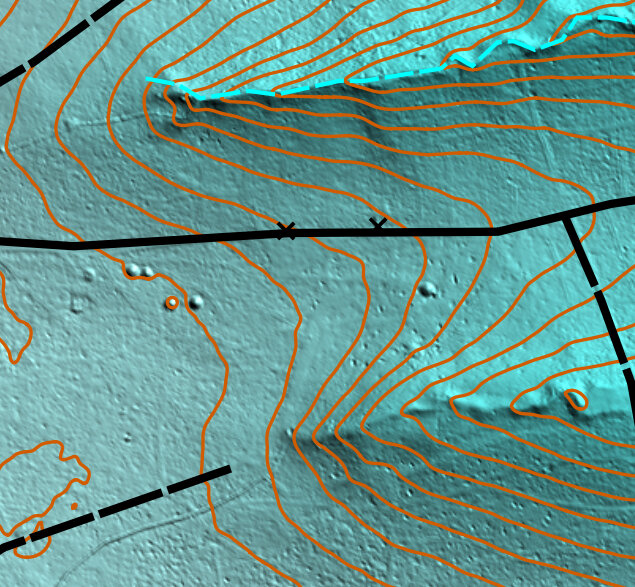
On the right, the same area in a different Hill_Shading image we can more clearly see the unmapped trails running east-west.
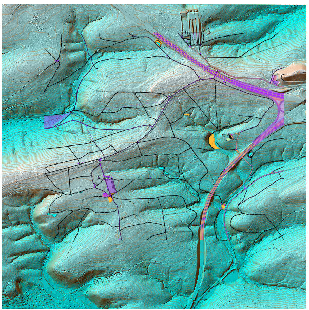
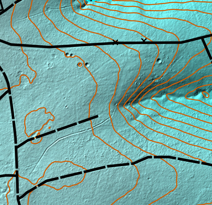
- Open the "Slope_Blue.png" image using the above procedure.
The 'Slope_Blue' template may help us to categorize certain slopes (white is steeper slopes, blue is flatter terrain). This is the same area as the one above.
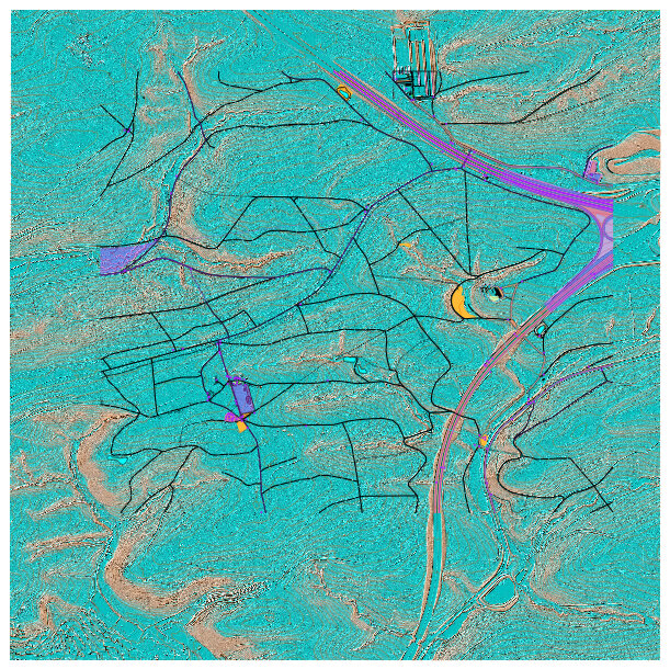
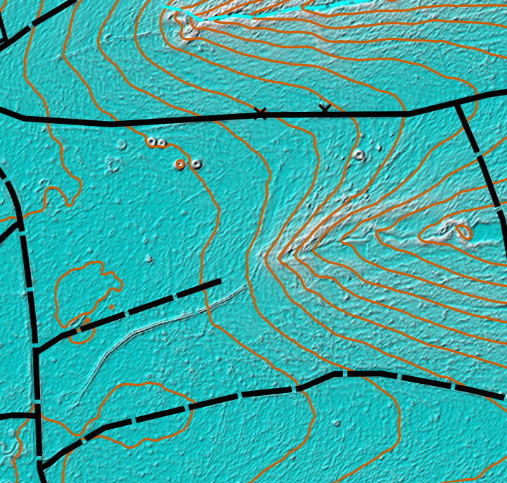
- Open the "Slope_Gray.png" image using the above procedure.
The 'Slope_Gray' template makes it easy to see the terrain (black is steeper slopes, white is flatter terrain). Again this is the same area as the one above. Sometimes one template will show a terrain feature better than another, so try different things.
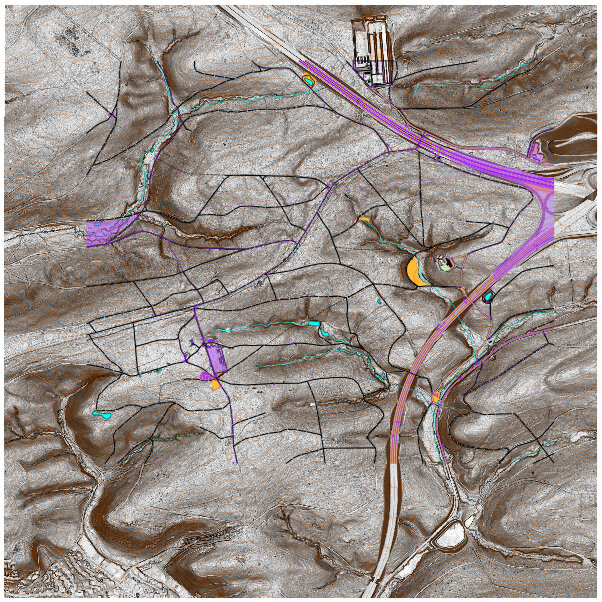
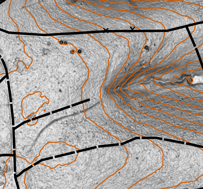
- Lastly, open the "Contours_0.5m_Raw.omap" file using the same above procedure.
NOTE: To see the detail of this template better, we will hide all the other templates, and zoom in quite a bit.
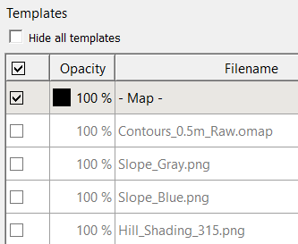
- Uncheck all the check-boxes except the "- Map -" and the "Contours_0.5m_Raw" templates.
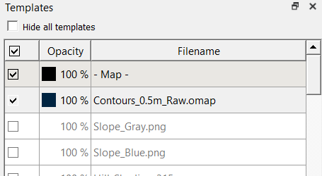
- Zoom in until you see the small purple contour lines between the brown normal-sized contour lines.
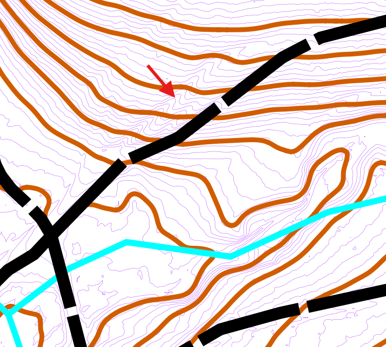
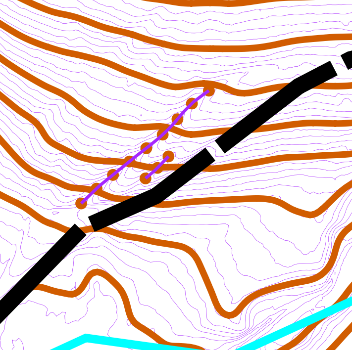
The 'Contours_0.5m_Raw' template reveals a lot more about the micro-terrain because it hasn't been smoothed like the 2.5m contour lines. Here we see a probable small erosion gulley (108) located north of the trail, which we'll need to field check.
- Ensure the map part is set to "default part".
- Draw a small erosion gulley (108) directly where we think it should be. Add a purple line telling us we need to field check it. Upon closer examination there may also be a small erosion gully right next to it, so mark that one too with erosion gulley and the purple line.
- Uncheck the 'Contours_0.5m_Raw.png" check-box.
- Select "File --> Save" to save the map in the park folder.
3.7 Orthophotography
OPTIONAL STEP
As mentioned in this section, digital orthophotography is useful, but uses a lot of memory, and it may not contain the level of detail available with LIDAR data to justify it's use in the field. It can be helpful at home, however, for discovering big differences between OSM data and satellite imagery.
- To demonstrate its use, we will open one of the files we downloaded, "Orthophotography/dop20rgb_32_504_5396_1_bw_2022.tif" using the procedure described in the the above section.
This particular image is 73 MB in size, but only covers about one ninth of our map.
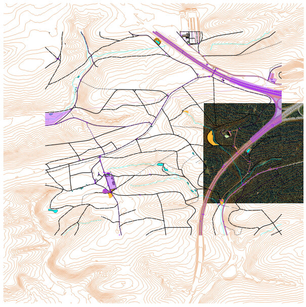
NOTE: Experiment with adjusting the opacity of templates, to compare your map with other layers.
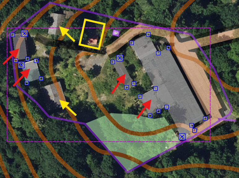
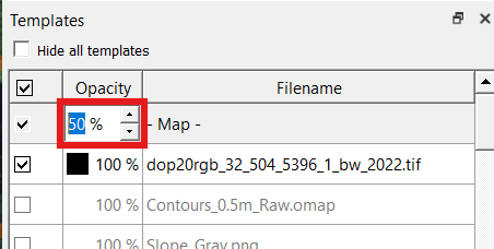
- Decrease the 'Opacity' for the Map from 100% to 50%.
By comparing the OSM buildings with the imagery, we can see that some buildings were mapped (red arrows), and some were omitted (yellow arrows). The imagery does not help us identify what should be mapped in the yellow box. We would still need to field check all these buildings in case some of them are no longer standing. Since the imagery is dated 2022 and the LIDAR data is from 2019, the whole place could be different now (in 2025).
We also are unable to determine what the purple line means in this area. Is it a fence, or some sort of property boundary line? Similarly, we don't know how to interpret the small purple square next to the yellow box.
- Increase the 'Opacity' for the Map back to 100%.
Zooming in on one of the buildings we looked at earlier, it may seem as though the building is not perfectly aligned with the imagery.
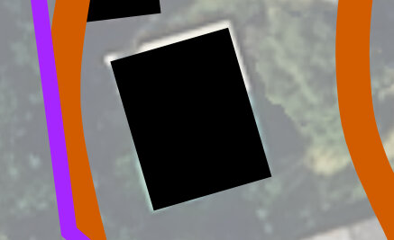
Although the zoom is maybe 64x when we examine this building, if we notice multiple buildings with the same issue, we might be tempted to start shifting all the buildings and roads so they conform to the orthoimagery better. DO NOT fall into this trap! Firstly, the numerous subtle adjustments required for such a fix are too many, and would take too long. Secondly, at this zoom level the size of the adjustment is just too small and the changes would be insignificant on the map at orienteering-scale (zoom level 1).
The lesson here is to first focus on easy fixes like putting things on the map, rather than spending a lot of time and energy making miniscule adjustments to the map which might have no bearing on the end result.
If you still feel as if the orthoimagery is inaccuratly geolocated, realize that the LIDAR (i.e., from other templates) is probably more accurate than the orthoimagery. So use LIDAR-based templates to update geolocational info for your objects first, and orthoimagery second.
- Select the orthophotography image in the Template Setup Window and click the "Remove" (red minus) button to remove the template from the map.
- Select "File --> Save" to save the map in the park folder.
3.8 Crop Outside Areas
- Note how the contours and other LIDAR-derived templates (red box) extend past the boundaries of the OSM data we downloaded (yellow box).
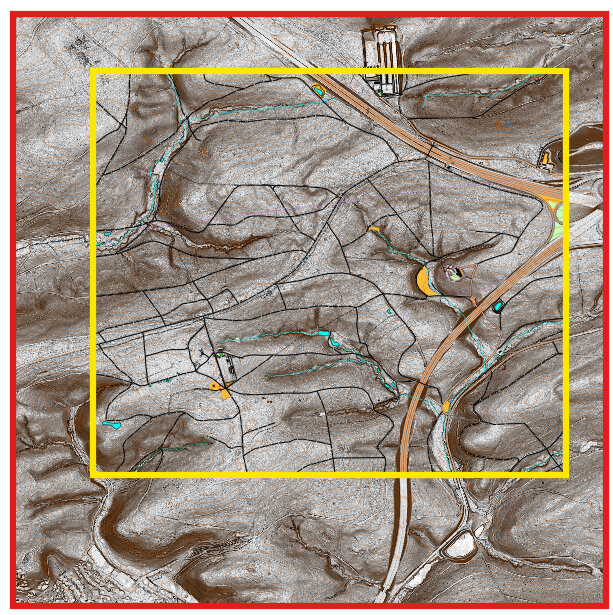
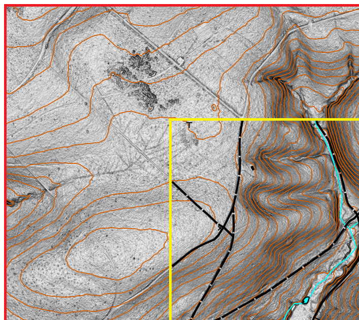
We will crop the contour lines that are outside the OSM area, and create a masking area which hides the LIDAR templates outside the OSM region.
- In a notepad app, open the "Notes.txt" from when we first downloaded the LIDAR.
- In the 'Notes.txt', highlight the "OSM Range (UTM)" line.
- OSM range (UTM): north 5395678 to 5397718, east 502415 to 504780
- Switch back over to OpenOrienteering Mapper.
- Set the map part to "Topos".
- Click the "2 Line" (purple line) symbol.
- Click the "Draw Rectangle" (square) button.
- Make a rectangle which approximately surrounds the OSM map area on your map, by left-clicking at the top-left and top-right, and right-clicking at the bottom-left of the area.
- Select "View --> Display coordinates as… --> UTM coordinates".
- Select the "Edit Objects" (arrow) tool.
- Zoom in on each corner.
- Using the mouse and looking at the coordinates at the bottom-right of the window as you move the mouse, move each boundary until they match the range we downloaded for OSM data. In this example, the bottom-right corner should be at UTM coordinate '504780, 5395678', which almost matches the OSM data boundary.
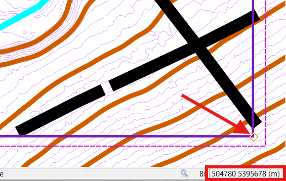
We should have a rectangle that surrounds only the OSM data part. We will next use this rectangle to crop (delete) all the contour lines that extend outside this OSM area.
- Click the 'Cutout' button.
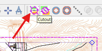
NOTE: The boundary box will appear red. It is warning us that if we press enter, it will delete some content.
- Press 'Enter'. All the contours outside the OSM area should be gone now.
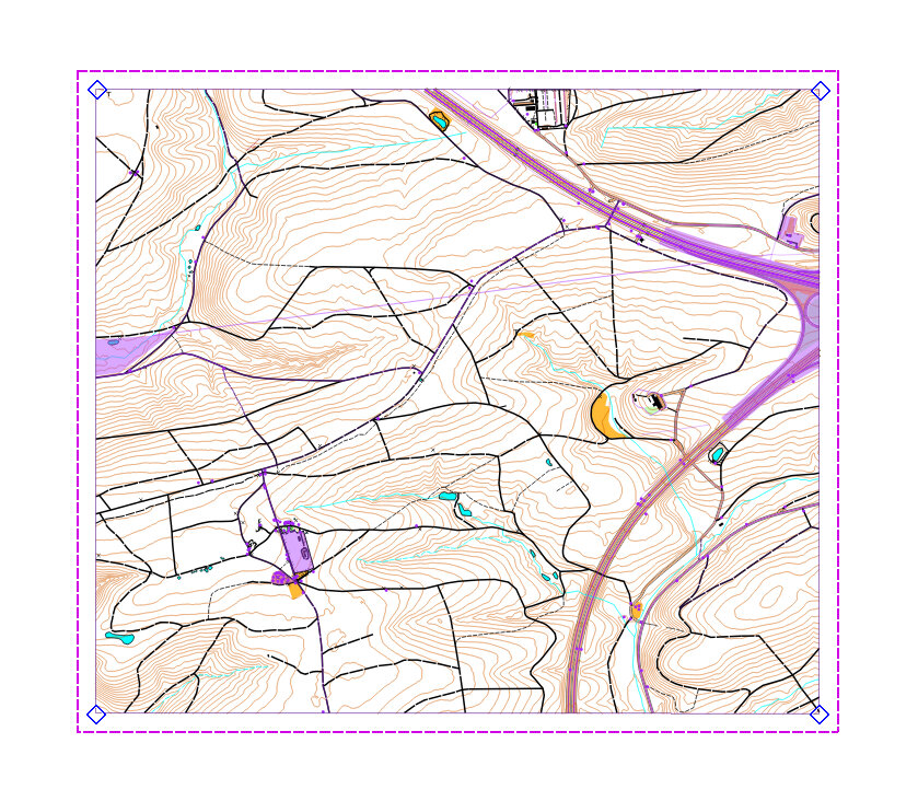
Now we will enlarge the purple rectangle, so that the area encloses the extra LIDAR data surrounding the OSM data.
- Zoom into the top left of the purple rectangle.
- Select the purple line and right click along the line.
- On the mouse menu, select the 'Cut object' (Scissors) tool.
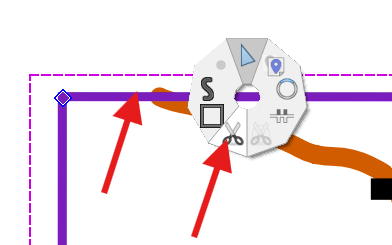
- Left-click twice along the top portion of the line.
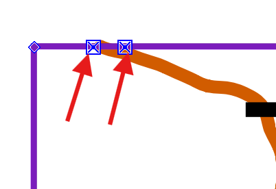
- Select the newly cut short line, and click "Delete' to remove it.
- Select the "Draw path" (S) tool.
- Click at one end of the line.
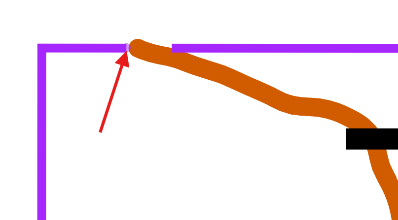
- Keeping a little spacing from purple line, and moving counter-clockwise around the purple rectangle, click outside each corner and rejoin at the other side of the cut purple line.
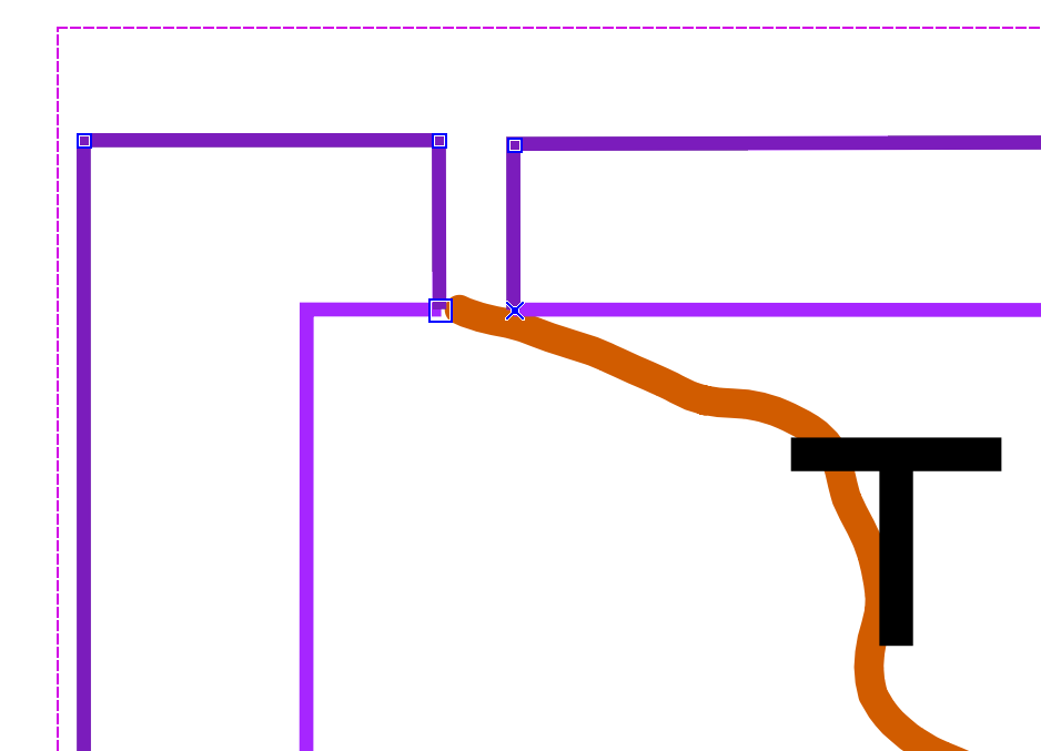
- Select both purple lines, then hit 'C' to connect the two lines together (the line is now a concave-shaped area).
- Select the "3 Area" (purple area) symbol.
- Click the "Switch symbol" tool so switch the purple line to a purple-shaded area.
The purple lines should now be a purple area.
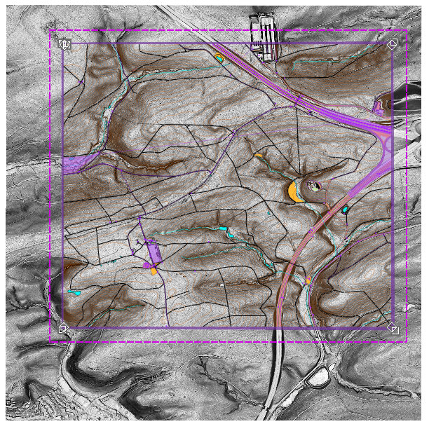
- Turn on another LIDAR template like "Slope_Gray" template.
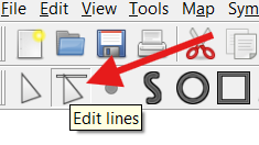
- Click the "Edit lines" tool.
- Click and drag each exterior side of the purple area, and extend the area until it covers the LIDAR templates.
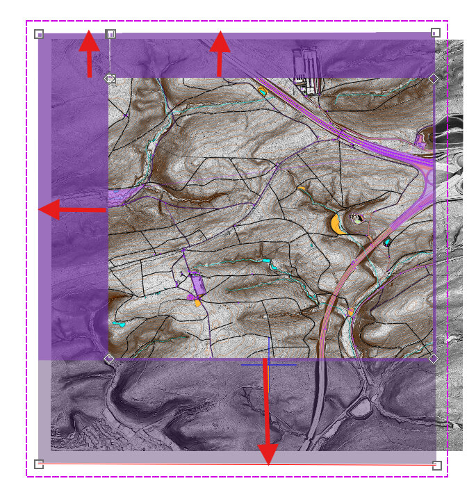
Here's what our map looks like:
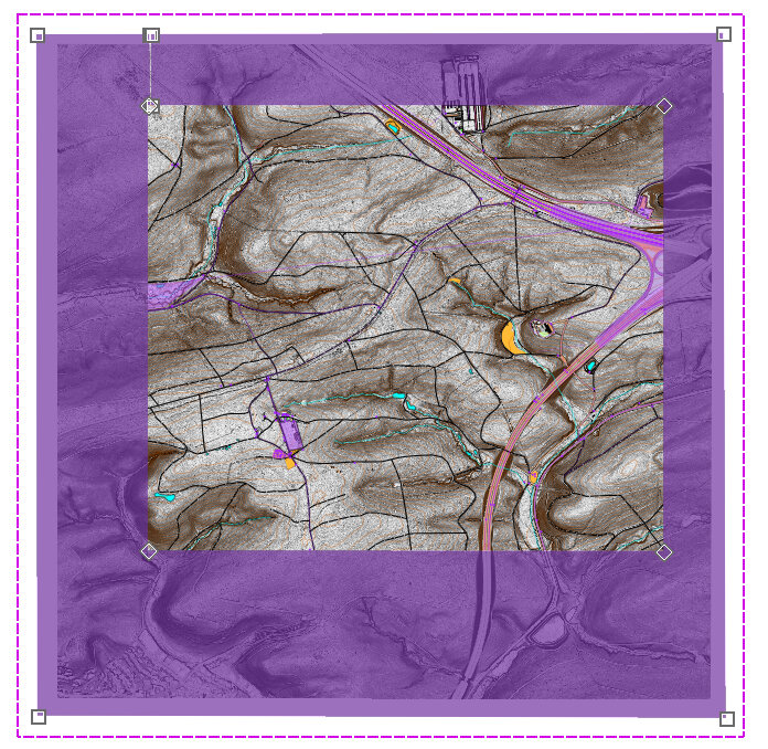
- In the top-left corner, zoom into the cut part.
- Click the 'Edit Objects' (Arrow) tool.
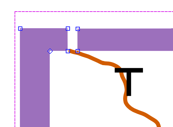
- Click and drag the top right corner on top of the top left corner.
- Click and drag the bottom right corner on top of the bottom left corner. (Here we see the yellow arrow showing a portion of the movement; we need to move one point on top of the other)
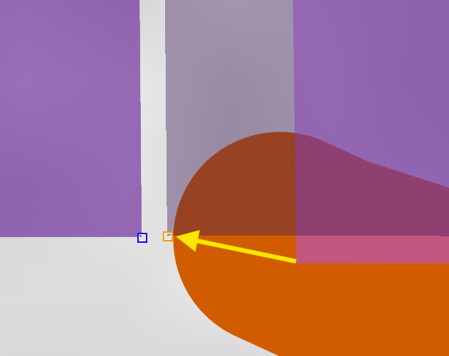
NOTE: We want the two sides to perfectly match up, so nothing is visible through the cut area.
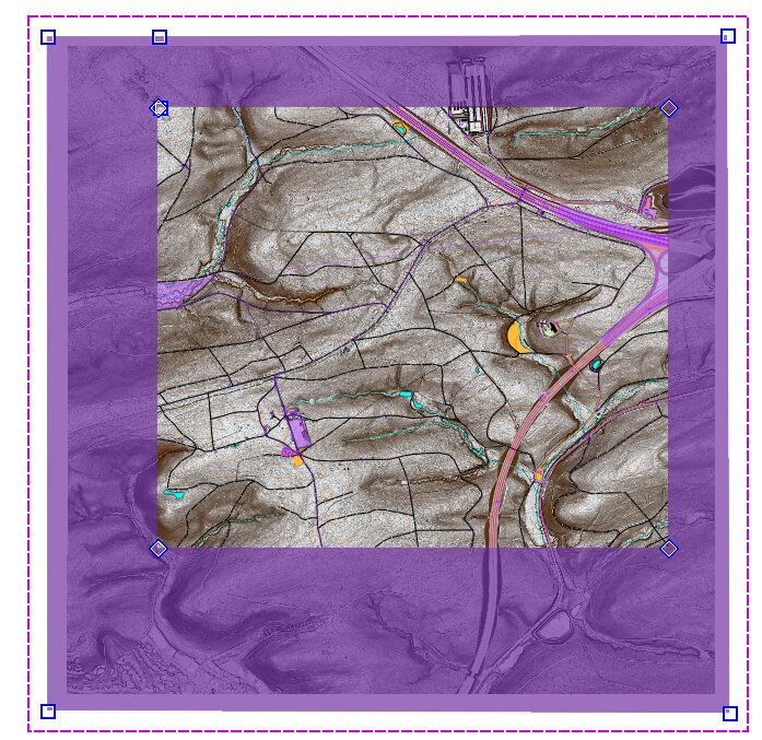
- Click the Forest button (symbol 405).
- Click the "Switch symbol" tool so the purple area switches into a white area.
- Deselect all, and switch to the "default part" of the map.
- Select "File --> Save" to save the map in the park folder.
Our map now looks like this: the templates are hidden around the exterior of the OSM data (thanks to a forest area masking those areas), and we've cropped (removed) the contours that were in the 'Topos' part.
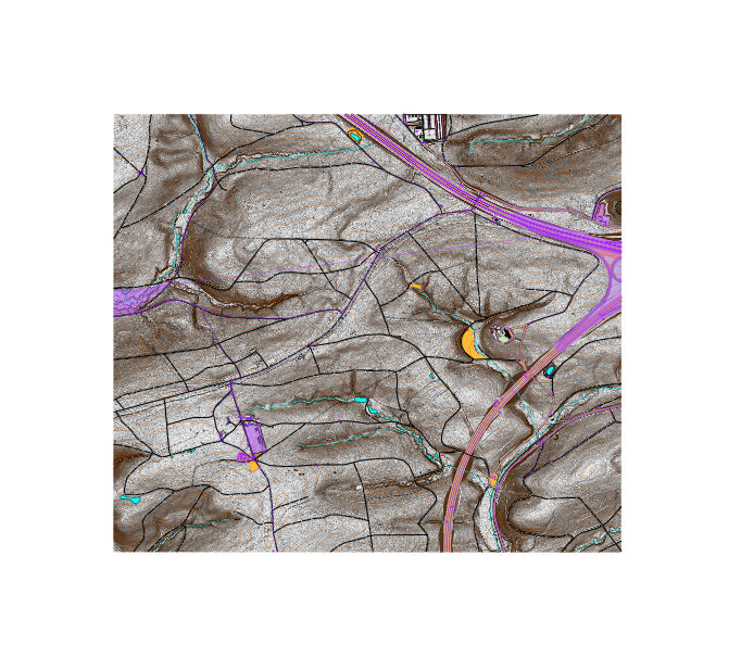
3.9 Reference Point
OPTIONAL STEP
Creating an unofficial reference point common to all parts is an optional step which will help us later on, when we want to move many objects (i.e., trails or purple stuff) away from the map on a temporary basis, rather than deleting the objects outright. With a reference point common to all parts, we will be able to move all the objects back to the same exact spot, if we're careful.
NOTE: Complete the previous sections concerning making different map parts, importing smooth contour lines, and cropping contour lines before continuing with this section, otherwise cropping the contours will remove the reference point as well!
- Change the map part from whatever it is to "Grid".
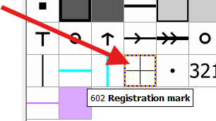
- Select the "602 Registration mark" Symbol.
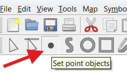
- Select the "Set point objects" (dot) tool.
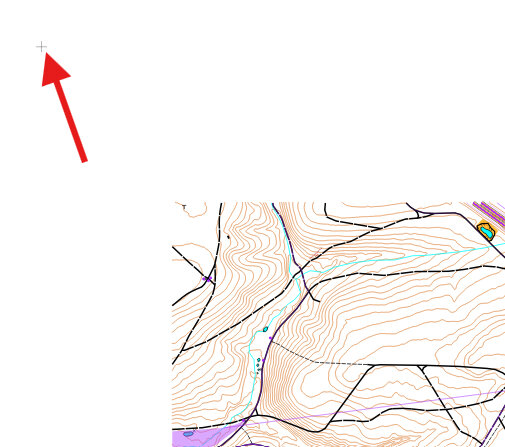
- Pick an arbitrary point that is at least 500m above (north) and 500m to the left (west) of all the other objects on the map (including contour lines and any OSM object data).
NOTE: If you plan to eventually expand the map in the north-west direction, choose an arbitrary point furthest-most away from all other objects in a different direction. Do it this way to facilitate micro-adjustments when moving objects. (In OpenOrienteering mapper, we move objects by clicking and dragging the orange dotted-line selection-box that surrounds it; the edge of the selection box is always at the outer edge of ~all~ selected objects).
- Left-click once on the map in the location you selected. It should leave a 602 'registration mark' symbol there, although you may need to zoom in to view it. Remain zoomed out.
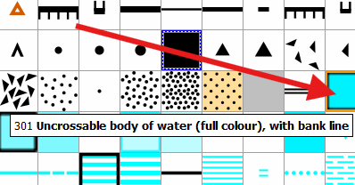
- Select the "301 Uncrossable body of water" Symbol.
- Select the "Draw Paths" (S) tool, at the top left side of the toolbar.
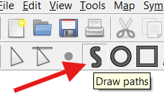
- Left-click immediately southeast of the 602 registration mark.
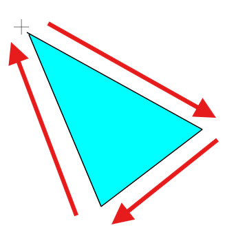
- Move the mouse southeast and left-click two times, to create the bottom side of a triangle.
NOTE: If you selected a different direction to place your reference point, position your triangle so that it is in between the rest of the map, and the 602 registration mark, and pointing towards the 602 registration mark.
- Return the mouse to the first corner of the triangle and right-click as close as possible to the top end of the triangle.
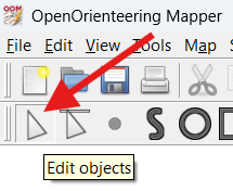
- Click the 'Edit Objects' (arrow) button at the top left.
- Left-click over the triangle to select it.
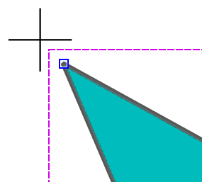
- Zoom in on the top-left corner of the triangle.
- The ends of the triangle pathway must contact each other. Left-click and drag the X so that it meets the other (squared) end of the line.
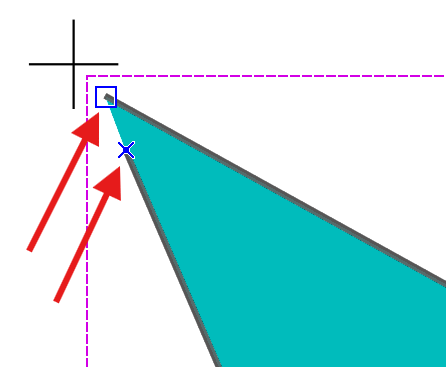
- Press 'C' to connect the lines and turn the path into an area.
- Left-click and drag to select both the 602 registration mark object, and the triangle area 301 Uncrossable body of water.
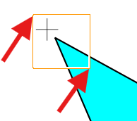
- Select "Tools --> Duplicate".
NOTE: The duplicate tool copies objects and keeps the location the same.
- Select "Map --> Move selected objects to" and select "Purple".
- Repeat the last three steps for each of your map parts. In our example, for map parts 'Purple', 'Vegetation' and 'Topos'.
- Select "File --> Save" to save the map in the park folder.
Having these reference points will allow us to move entire sections of the map out of view, on a temporary basis. As an example, we will (temporarily) move everything Purple to the left of the map in the next few steps
- Change the map part from Grid to "Purple".
- Press CTRL+A to select all objects (in Purple part).
- Left-click and drag until all the objects are significantly left of the map.
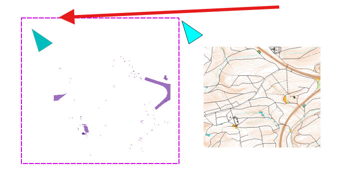
NOTE: It may help to draw a colored rectangle on top of the moved objects, so we know the missing purple objects have been moved left of the map.
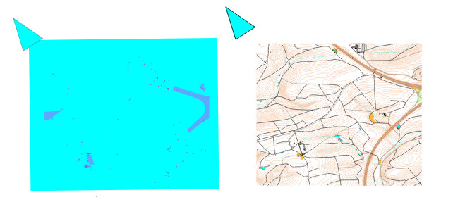
- To return the objects to how they were before, select all, left-click and drag it back until the triangle and registration points exactly match up with the original in the grid part.
NOTE: You can be extremely accurate when moving these parts by selecting all the symbols you want to move, then zooming in as far as you can on the left/right/top/botton edge of the registration point, and slowly moving the selection until the corresponding edge lines up perfectly with the edge on the 'Grid' part.
Using this technique we could make several changes to a map, without having to move the purple objects back before each save, and without having to re-import symbols a second time from OpenStreetMap. Although, we would want to move the purple stuff back to its correct placement before importing more OSM data, so patching together the two sides is easier. Also, every once in a while the OpenStreetMap data is updated, and you may want to re-load OSM data to see if any changes have been made since your last version.
- Press CTRL+Z or the 'undo' (yellow left arrow) button, until the purple objects you just selected return to their previous location.
NOTE: If you make serious changes and you are not sure how to proceed, you can always close without saving, and re-open the last saved file. Using the "Map --> Rotate map" menu option cannot be undone, therefore always save the file before you rotate the map.
Because of these and other issues, you may want to consider using a version control system like github to standardize updates to your map. If you do not use github, the best practice for mapping is consistently using a file-naming convention which includes the date of update, and keeping your files and folders well-organized. At the very least, because the relevant data in your map is now all in a single file, make a back-up copy every now and then!
3.10 Hide Purple Part
Once we have all the templates loaded, we can begin to edit our map. To simplify things, we will remove all random purple lines that we are not interested in.
We will keep only a portion of the purple lines, by copying the only the relevant sections of those lines to the 'default part', and moving the remaining purple stuff out of the way.
NOTE: Pending a 'hide part' function in OpenOrienteering Mapper, we will hide the purple part by moving the purple objects out of the way!
- Note how several of the purple lines directly overlie roads or trails.
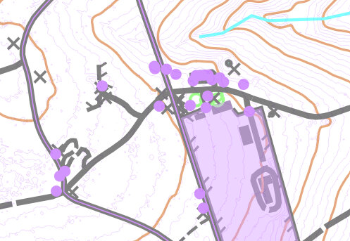
- Scan the map for any purple lines which do not overlie a road or trail. These ones might be worth keeping.
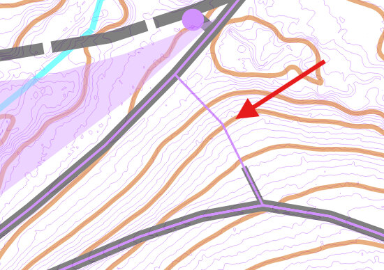
- One by one, select those purple lines, cut them at each end if necessary (using the mouse menu --> scissors tool) where they no longer override a road or trail.
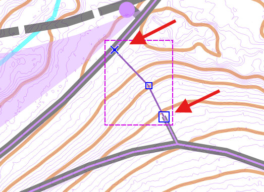
- Press 'D' to duplicate each part.
- While each part is selected, click "Map --> Move selected objects to --> 'default part'.
- Move the remaining purple stuff (in the purple part) off to the side, as described in this section. It will be easier to edit the rest of the map without all the purple stuff present, and by moving it rather than deleting it, we still have access to it if we ever wanted to reference it later on.
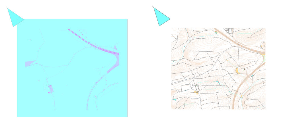
- We're left with only a few purple lines in the default part, which we will need to field check.
NOTE: By leaving these purple lines in the 'default part' it helps me to remember to field check them. When I field check them, I may simply delete the purple line if nothing is there, or I may change it into another object, such as small trail or fence, whatever is actually there.
3.11 LIDAR to Mapped Roads
The easiest way to update roads and trails is to use the LIDAR-derived templates, such as Hill_Shading_XXX, Slope_Gray and even Slope_Blue, combined with ~30% Map opacity.
- Turn on Hill_Shading_315 template
- Find a spot where the trail or road appears slightly off the trail as depicted by the LIDAR-derived template.
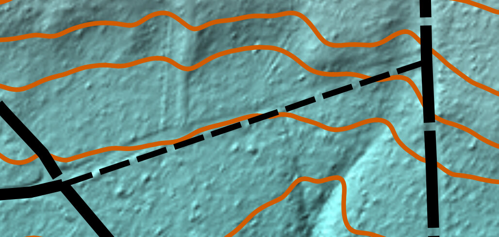
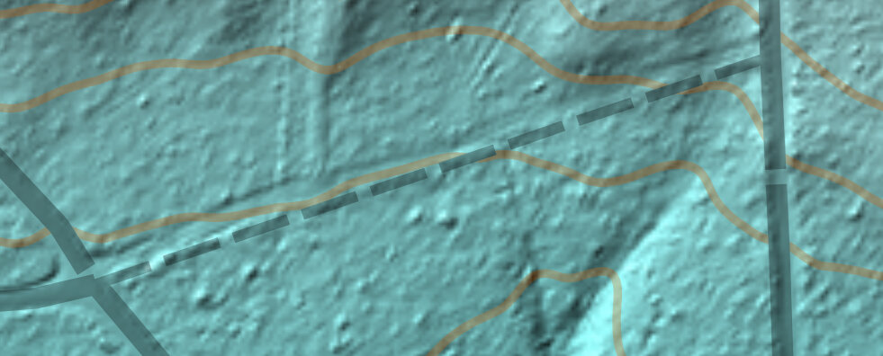
- Adjust the "- Map -" to 30% opacity.
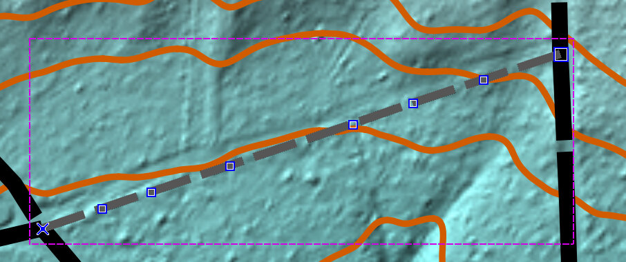
Select the object, then while holding CTRL, left-click the linear object to create new intermediate points along the line.
Release CTRL and click and drag the points to reposition the line over where the LIDAR data indicates the road or trail should be.
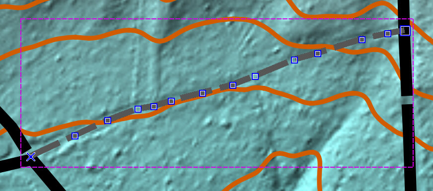
By holding SPACEBAR while left-clicking over an already-existing point along the line, we can change that point to an intersection point. (or tower point for power lines) [not demonstrated with this example]
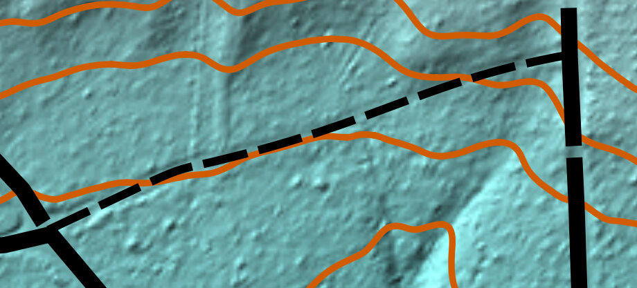
Select a line that you have shaped to match the LIDAR, then click 'N' to turn the line into a series of curves.
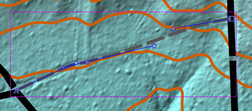
Here we see the end result, more accurately matching the terrain. It does not have to be perfect. It's much better, and will make for a great orienteering map!
3.12 LIDAR to Unmapped Trails
In this step we examine LIDAR shading images to see if there are trails (or roads) that are not mapped on OSM, however still clearly exist in the terrain.
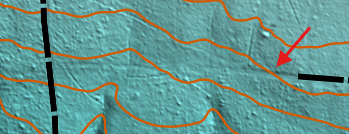
- Turn on Hill_Shading_045 template.
- Examine the map for possible trails that are not included on the OSM map.
- Select the 'default part' of the map.
- Draw a purple line over the unmapped section of the trail, where it appears the trail still exists in the LIDAR imagery.
NOTE: In this image, I chose to leave the center part blank, because the LIDAR was not strong in that area. When I go to field check this area, I may make the trail connect, or leave it separated, depending on what the actual trail looks like.
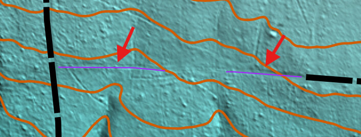
- Repeat the above four steps for each of the three remaining Hill_Shading_XXX images (135, 225, 315) looking for and marking possible trails with purple line.
The point of marking it with purple is to mark it for field checking. It will need verification before we use it in an actual event. For things that look like roads, I find it easiest to simply mark it with a purple line, and determine how to mark it when I am in the field.
NOTE: It takes some time to get good at identifying a certain on-the-ground feature with it's equivalent in orienteering symbol, but you will get better with experience. Before field-checking the sites, examine the various possible symbols by reading about the differences at the O-Map Wiki page. It's easier and more realistic to only focus on a few similar symbols, rather than every symbol you might come across in the field.
- It may be worthwhile to examine the map with the Vegetation Height template active, to see possible locations of narrow rides (symbol 508). We may have to map every one of these if we want our map to be absolutely correct.
NOTE: Although some of the narrow rides in this image have not been marked, the narrow rides are so prominent on this image we would probably want to draw purple lines along each of these, to field-check and confirm they are still mappable as narrow rides (symbol 508), something else, or nothing at all.
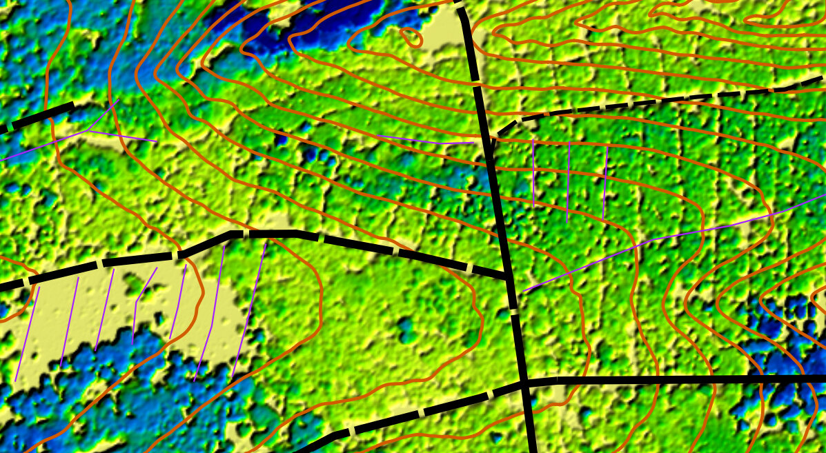
Mapping these rides may mean walking them, and then loading the GPS tracks as templates into OpenOrienteering Mapper. If you decide to do that, be sure to use LIDAR data to refine your GPS tracks, because the LIDAR data is probably more accurate in general than your GPS is.
- We should now have a bunch of purple lines in our 'default part' for us to field check later on.
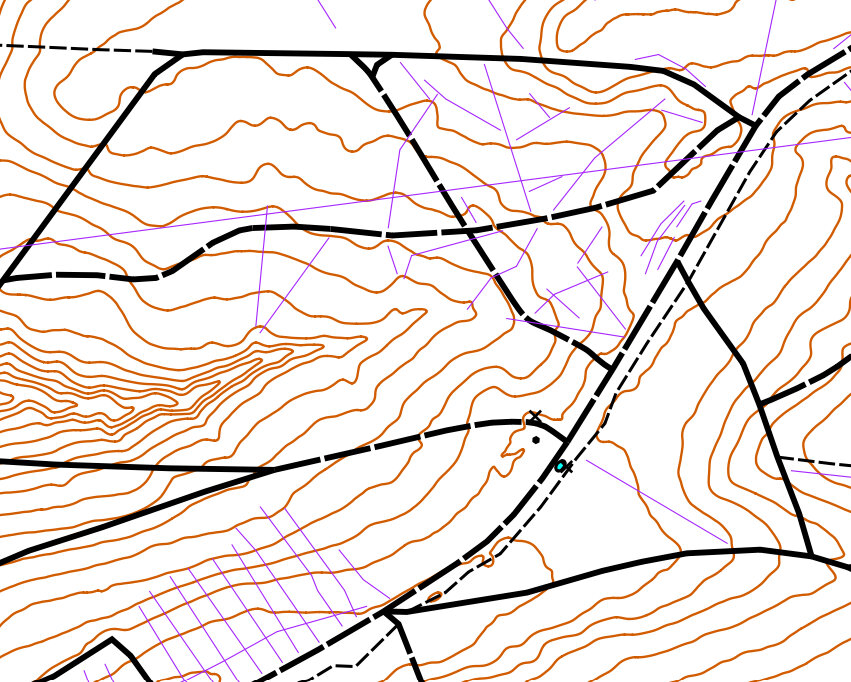
NOTE: Ordinarily we would recommend adding points like in the previous step, and curving the lines to make them fit the LIDAR topography better. But for unmapped trails/roads, it is better to wait until field-checking them, and confirming they exist, before spending a lot of time perfecting how they appear on the map.
3.13 LIDAR to Linear Features
By examining small repetitive patterns in the micro-contours, we can identify the location of probable small erosion gullies (symbol 108), erosion gulleys (symbol 107), possible narrow marshes (symbol 309), and other micro linear features that we would ordinarily include on an orienteering map.
- Load the 'Contours_0.5m_Raw' template, and select the 'default part' of the map.
- Zoom in looking for signs of small erosion gullies.
NOTE: Once you determine what a small erosion gulley or erosion gulley looks like on the micro-contour template, it will help you to identify this terrain feature on future maps.
- Mark them with the small erosion gulley (symbol 108), and also with purple line, so we know to check them in the field. (map is at 50% opacity to allow us to see the micro-contours.)
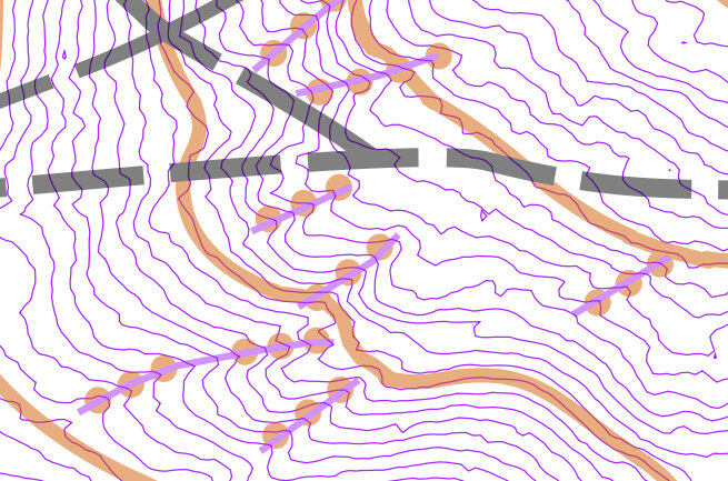
- Look for erosion gulleys and mark them in the same way. (map is at 50% opacity so we can see the steep contours.)
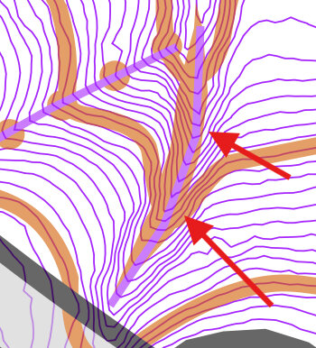
The goal of making these additional edits, is to do as much preparation before we head out into the field, so that when we are in the field we know exactly what we are looking for, and exactly where to look, and we have already edited it to match the LIDAR terrain as accurately as possible, so all we have to do in the field is confirm it.
NOTE: Any strategy that can save you time in the field is going to help you complete your map sooner. This is because edits in the field can often take significantly more time than at home, (perhaps because you're using your fingers on a mobile device). In the field, you spend a significant chunk of time just moving from place to place, and marking other unmapped things like rootstocks or vegetation areas. If you have to do a bunch of edits while you're in the field, it means you cover less ground walking around. Field-checking is time consuming, so prepare as best as you can before venturing out in the woods!
- Next, examine already-mapped drainage routes such as small crossable watercourse (305) and narrow marshes (symbol 309) for sections that are imperfectly mapped.
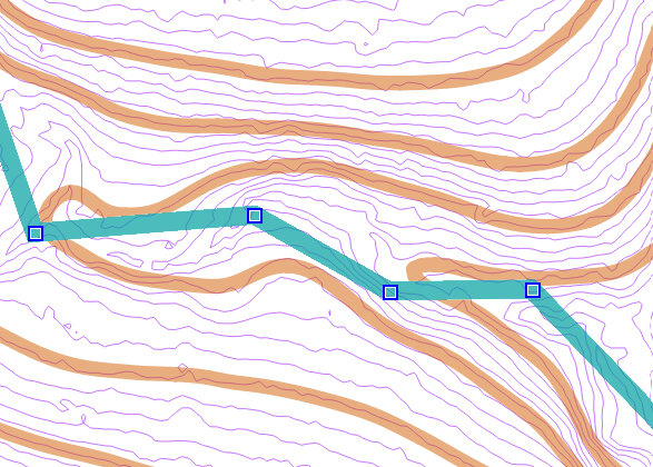
- Go through and add points on each line (by pressing CTRL while clicking on the line), and move the points to make the line match the terrain better, so they follow the pathway of lowest elevation.
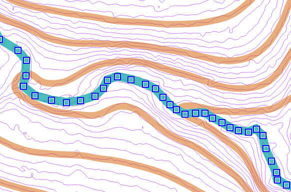
- Change the line to a curve (by selecing it and pressing 'N') to make the hydrography/drainage features look better.
NOTE: Be careful to only apply curves to lines that should be curves. Lines with distinct corners such as rectangular areas and fences usually should keep their corners and not be curved.
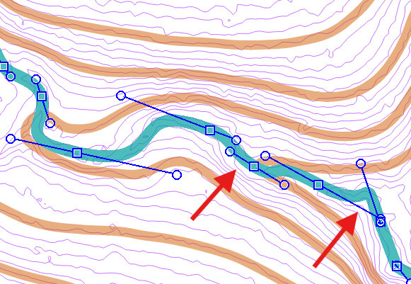
Looking closer at the above image, we see a few spots where the edits we made now appear to be slightly inaccurate. Although we could try fooling with the curve to make it look better (possibly by adding new points and adjusting the lines), it might not be worth it. At this zoom level, we are eleven times more zoomed in than if we were to hold the map in our hands (at 100% zoom level). This is what it will look like at 100%.

Let's move on to other stuff, before we go "too far" in editing this section of hydrography.
- We now have even more linear features that need field-checking, and it will make the process of field-checking much quicker by having a plan of where to go!
3.14 LIDAR to Micro Features
- Load 'Hill_Shading_045' or 'Hill_Shading_315' template, and examine your map for the presence of pits (symbol 112) or small depressions (symbol 111).
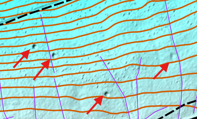
By zooming in and turning on the 'Contours_0.5m_Raw' template, we should be able to identify which feature is there, and mark it for field checking.
- Mark each symbol with a purple dot to indicate that it needs field checking.
NOTE: You may wish to place the purple dot slightly to the side of the object so it does not interfere with your ability to see it on the map.
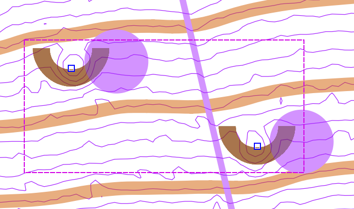
- Examine the entire map and mark anything that could be a possible pit, small depression, elongated knoll (symbol l10), or small knoll (symbol 109).
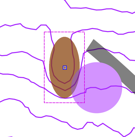
- It may be worthwhile to take some of the Hill_Shading templates with us when we field-check to determine if these bumps are anything significant such as broken ground (symbol 113), or just anomalies in the LIDAR data.
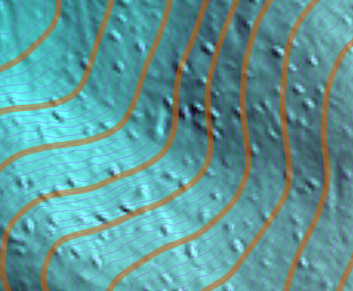
It is possible that when you field-check an object, it turns out to be something else such as a boulder (symbol 204) or prominent vegetation feature (symbol 419). As long as you mark it correctly when you field check it, or take a photo of it so you can confirm with outside sources on how to mark it, you're good!
Alternatively, compare your feature on the ground with the explanations in the O-Map Wiki page (or other resource), to determine how best to map something.
3.15 LIDAR to Banks & Cliffs
A similar process can be used to identify areas of earth bank (symbol 104), or cliff (symbol 202) or impassible cliff (symbol 201).
- Load 'Contours_0.5m_Raw' template and examine the map for any bunches of contour lines close together indicating steep slope.
The areas pictured below are likely earth bank or cliffs, but need to be field checked to confirm accuracy. Compare to the description in the O-Map Wiki page (or other resource) to determine accuracy.
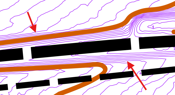
NOTE: Once you determine what one earth bank or cliff looks like on the micro-contour template of your park map, it will help you to identify other earth banks or cliffs on your map.
In this case, I had to field check it before realizing that one of the banks had some steep rocks on it, therefore making it an impassible cliff (symbol 201). And by identifying how close 0.5m contour lines had to be to one another, to be assigned the earth bank symbol, I could go through my map and assign the earth bank symbol to a few other areas. I also had to field-check those areas, but it helped me to understand the level of steepness required for earth bank.
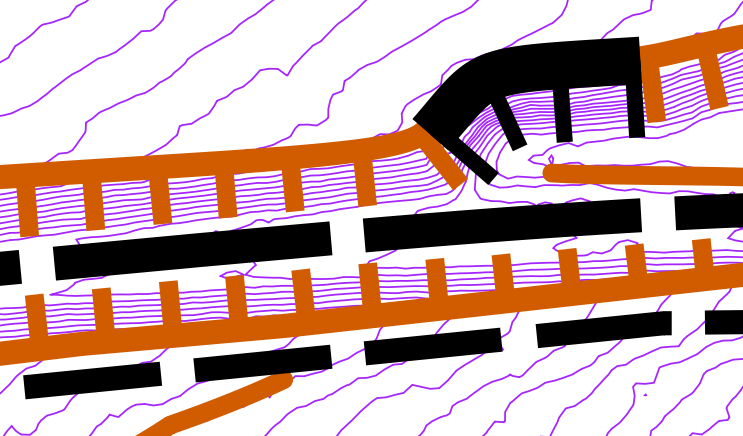
NOTE: Make sure you use the proper direction (the hatch marks should face downhill). Also, keep in mind that some extra edits may be needed to keep the map ledgible for competitors. If you are unsure of which edits need to be made for ledgibility, check out the rules at the O-Map Wiki page.
3.16 Conduct Field-Check
The goal of field checking is to verify anything on your map that needs verifying (which should be everything at the beginning), and also add new objects that should be on the map, that you come across while field-checking.
- Install the mobile version of OpenOrienteering Mapper to your mobile device. I had to download it outside of the Google Play Store, and install it by copying it to a folder on the mobile device.
- Copy the map file and most of the associated template images to the proper folder on the mobile device.
Whenever I prepare to conduct a field check, I deliberately rename the map file that I left on my computer as "backup_map" so that I don't accidentally start making edits to that one, when the one I will be using is the one on my mobile device.
NOTE: OpenOrienteering Mapper requires maps and templates are located in a subfolder in the OpenOrienteering Mapper app folder, which on my device is located at "Android\data\org.openorienteering.mapper\files". The only way I was able to copy the files was through USB cable. After you plug in your device, you may need to adjust your mobile device's "USB Preferences" to enable "file transfer".
Ideally, all your templates (excepting orthophotography) were loaded from the 'park' folder, which means they were in the same folder as the map itself. If they were in other separate folders, when you go to open them on your mobile device they may not be found. You'll get an error message and won't be able to see that template, but otherwise the map should open fine.
Some people use an external GPS device when mapping for increased accuracy while mapping. One mapper reports success using the Ardusimple "RTK Portable Bluetooth Kit" interfacing directly with OpenOrienteering Mapper. More information on this device can be found at RTK Portable Bluetooth Kit. This device is especially appealing to me because it is relatively cheap at a few hundred Euro, supports bluetooth and USB, and also supports NTRIP for corrections, which is an exciting add-on technology allowing even more accurate measurements, depending upon your access to NTRIP data.
My limited experience using a low-end $100 device, is that the external GPS provides additional peace of mind, but is not vastly superior to my phone's built-in GPS system. I have a Garmin Glo with the 'Bluetooth GNSS' android app installed on my phone, and I have to enable the phone's "developer options" and select "Developer options --> Select mock location app --> Bluetooth GNSS" for it to work. I am currently tempted to buy a more expensive external GPS but will hold off until it's cheaper. Some newer mobile devices support multi-frequencies for GNSS, meaning they can receive and process GPS, Galileo, GLONASS and Beidu signals, theoretically increasing accuracy. This is a simplified explanation so it may be incorrect.
- Go into the field and verify certain things are where they are.
NOTE: When verifying/updating locations of objects and features on your map, try to incorporate more than just the GPS location for it. For instance, if a particular object i.e., a cairn (symbol 526) is between two small knolls (symbol 109), turn on "record my tracks" on the OpenOrienteering Mobile app and walk around the two knolls, and compare that GPX tracks to where the objects appear on your map. If the tracks are further away for whatever reason, maybe the map is more accurate in this instance than the GPX tracks. Or maybe both the cairn and the two small knolls should be shifted slightly in one direction. In other words, try to consider multiple factors before relying solely upon the GPS location for placement of an object, because GPS may not be the most accurate in all circumstances. An alternative to using other objects, is to visit the particular object on two separate occasions, to see if your GPS indicates a slightly different location the second time. If this happens, you may consider placing the object in between those two points - take an average of where the GPS said it was at on two different occasions.
- If you come across unmapped trails, it may help to walk the trail with your mobile device (assuming you have decent GPS accuracy) and view your GPX tracks later on. When you enable the "record my tracks" option, it will save the tracks to a GPX file in the folder with your map in it, which you can load as a template when you return home. A similar tactic can be used for those who have a GPS-enabled watch like Garmin.
- For sections of thick vegetation i.e., fight (symbol 410), one strategy is to walk around the area and duplicate its shape on your map as you do so. Enabling the "record my tracks" feature will make this easier.
- When you are done field-checking for the day, roughly mark where you were able to go using a purple line or area, so you can keep track of what still needs to be field checked. You can erase the area after you get home.
3.17 Finalize Updates at Home
- Once back home, copy the map file, and any new GPX files from the mobile device back to your computer.
- Load the GPX files as templates into the map file, if they are not automatically loaded. The GPX files may only exist if you enabled "record my tracks" on the mobile version of OpenOrienteering Mapper.
- Go through and make subtle corrections to any stuff you added or altered from the original map. For example, examine any new roads, and use LIDAR data to attempt to make them more perfect (see previous steps).
Inevitably there will be more things to verify. Mark them with purple markers for future field-checking. In some ways this is a never-ending process. But if you get to the point where you need to use your map for an actual event, it is possible to temporarily move the purple stuff out of the way. All you have to do, like in this section, is move all the purple stuff to a different 'part', and hide it or shift it to the side. If you decide to shift it to the side, make sure you create a reference point marker to help you move it back when you're done creating the event map.
- Have one or more other people review your map for accuracy. It will help for you both to venture into the woods and field-check stuff in person. Volunteers will do this to verify sections of the map especially before competitive events.
- Repeat field-checking and finalizing updates at home several times until you have refined as much of the map as possible.
- Review the rules for placement and readability, which are mentioned in the O-Map Wiki page. You may need to delete multiple objects if they are too close to one another, or simplify things in other ways to improve readability.
The goal of these last steps are to continually refine your map until it is almost ready for an event. However, there are some additional steps to do before your map is fully ready for an event.
3.18 Set Index Contours
Every fifth contour (depending upon contour interval) should be an index contour (symbol 102).
The reason why we waited until near the end of editing the map before creating index contours, is because the other objects and terrain may influence which contour you want to pick as index contour. Generally, when we talk about decisions here, we're looking to maximize user-readability.
- Decide which set of every fifth contours get changes to index contours.
- Select the "Topos" part.
- Go through and select every fifth contour line.
- Select "Index Contour" (Symbol 102).
- click "Switch symbol".
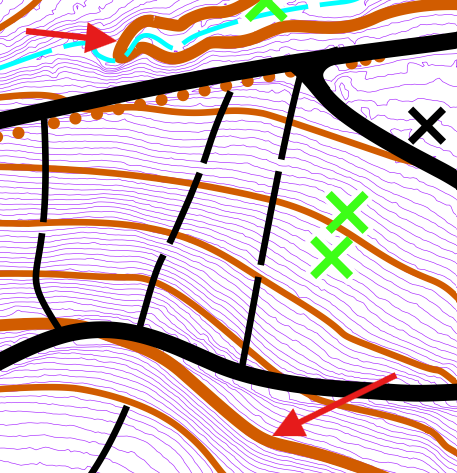
- Examine the rest of the map to ensure you have turned every of every fifth contour line into an index line.
NOTE: Pay particular attention to small hills and depressions which may also have to be changed to index contours.
3.19 Place form Lines
Let's say there are hills or topography in your park which is not reflected accurately on the map. for this we will add form lines (symbol 103).
- Add form lines to specific areas to improve readability.
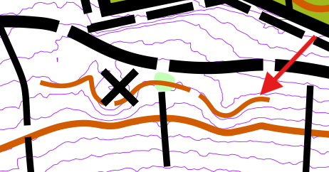
NOTE: Pay particular attention to small hills and depressions which may also have to be changed to index contours.